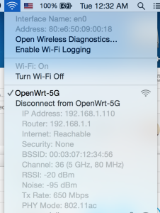
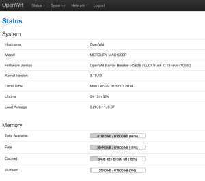
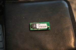
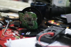
The Mercury MAC1200R (TPLINK WR6300) is one of the cheapest AC based routers on the planet, as I have a few AC devices I thought I’d buy one to try out. They’re available for under RMB120 or so online.
Mercury hardware is TPLink hardware, albeit using a different name. Same stuff, same factory, different casing.
The router has 64M ram, and 8M flash. CPU / Wifi AR9344 / QCA9882
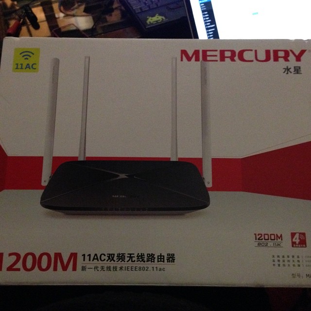
OpenWRT says it has support, so I had a quick go at taking a look at flashing one.
First steps:
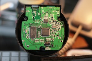
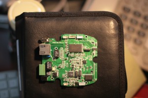
Open up the unit (remove the 2 screws underneath, then use a spare credit card or similar to jam open the plastic case).
The serial headers are to the right of the SoC.
You’ll need a rs232 to ttl or usb to ttl adaptor.
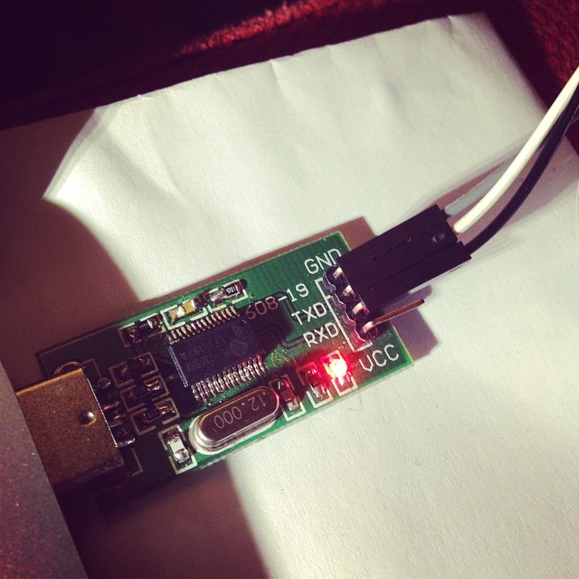
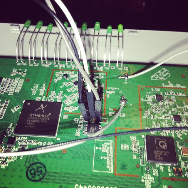
Pin 1 is GND
Pin 2 is TX (connect to rx)
Pin 3 is RX (connect to tx)
Pin 4 is VCC (don’t connect).
Port speeds are 115200,8,n,1
Connect up, and you should see a flurry of activity on boot.
To get into the bootloader (uBoot), you’ll need to type tpl
May take a few tries, so prepare to pull power and retry again, and again till you get in.
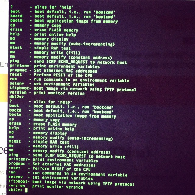
You’ll need a TFTPD server running on 192.168.1.100 to push files over. My Mac no haz ethernet (and Thunderbolt to Ethernet is crud), so I use my venerable X40 and tftpd software.
Firmware is up here. (Or you can compile your own) -> http://pan.baidu.com/s/1hqkVOfa
Firmware locations in flash (see below)
printenv

bootargs=console=ttyS0,115200 root=31:02 rootfstype=jffs2 init=/sbin/init mtdparts=ath-nor0:256k(u-boot),64k(u-boot-env),6336k(rootfs),1408k(uImage),64k(mib0),64k(ART)

bootcmd=bootm 0x9f020000

bootdelay=1

baudrate=115200

ethaddr=0xba:0xbe:0xfa:0xce:0x08:0x41

ipaddr=192.168.1.111

serverip=192.168.1.100

dir=

lu=tftp 0x80060000 ${dir}u-boot.bin&&erase 0x9f000000 +$filesize&&cp.b $fileaddr 0x9f000000 $filesize

lf=tftp 0x80060000 ${dir}db12x${bc}-jffs2&&erase 0x9f050000 +0x630000&&cp.b $fileaddr 0x9f050000 $filesize

lk=tftp 0x80060000 ${dir}vmlinux${bc}.lzma.uImage&&erase 0x9f680000 +$filesize&&cp.b $fileaddr 0x9f680000 $filesize

stdin=serial

stdout=serial

stderr=serial

ethact=eth0
Environment size: 686/65532 bytes
Upload to the uBoot
U-Boot 1.1.4--LSDK-10.1.389 (Apr 9 2014 - 15:23:02)
U-Boot DB120
Wasp 1.2
DRAM: 64 MB
Flash Manuf Id 0xef, DeviceId0 0x40, DeviceId1 0x17
flash size 8MB, sector count = 128
Flash: 8 MB
Using default environment
In: serial
Out: serial
Err: serial
Net: ag934x_enet_initialize...
No valid address in Flash. Using fixed address
No valid address in Flash. Using fixed address
wasp reset mask:c02200
WASP ----> S27 PHY
s27 reg init
: cfg1 0x80000000 cfg2 0x7114
eth0: ba:be:fa:ce:08:41
athrs27_phy_setup ATHR_PHY_CONTROL 4 :1000
athrs27_phy_setup ATHR_PHY_SPEC_STAUS 4 :10
eth0 up
WASP ----> S27 PHY
s27 reg init lan
ATHRS27: resetting s27
ATHRS27: s27 reset done
: cfg1 0x800c0000 cfg2 0x7214
eth1: ba:be:fa:ce:08:41
athrs27_phy_setup ATHR_PHY_CONTROL 0 :1000
athrs27_phy_setup ATHR_PHY_SPEC_STAUS 0 :10
athrs27_phy_setup ATHR_PHY_CONTROL 1 :1000
athrs27_phy_setup ATHR_PHY_SPEC_STAUS 1 :10
athrs27_phy_setup ATHR_PHY_CONTROL 2 :1000
athrs27_phy_setup ATHR_PHY_SPEC_STAUS 2 :10
athrs27_phy_setup ATHR_PHY_CONTROL 3 :1000
athrs27_phy_setup ATHR_PHY_SPEC_STAUS 3 :10
eth1 up
eth0, eth1
Setting 0xb8116290 to 0x30602d0f
Autobooting in 1 seconds
db12x>
db12x> tftpboot 0x81000000 image.bin
eth1 link down
enet0 port4 up
dup 1 speed 100
Using eth0 device
TFTP from server 192.168.1.100; our IP address is 192.168.1.111
Filename 'image.bin'.
Load address: 0x81000000
Loading: #################################################################
#################################################################
#################################################################
#################################################################
#################################################################
#################################################################
#################################################################
#################################################################
#################################################################
##############################
done
Bytes transferred = 3145732 (300004 hex)
db12x> erase 0x9f020000 +0x3c0000
Erasing flash... ............................................................
Erased 60 sectors
db12x> cp.b 0x81000000 0x9f020000 0x3c0000
Copy to Flash... ............................................................done
db12x> bootm 9f020000
It should boot into OpenWRT, you can flash from there.
...[long kernel bootlogs redacted]
- init complete -
BusyBox v1.22.1 (2014-12-15 18:46:26 CST) built-in shell (ash)
Enter 'help' for a list of built-in commands.
_______ ________ __
| |.-----.-----.-----.| | | |.----.| |_
| - || _ | -__| || | | || _|| _|
|_______|| __|_____|__|__||________||__| |____|
|__| W I R E L E S S F R E E D O M
-----------------------------------------------------
BARRIER BREAKER (14.07, r42625)
-----------------------------------------------------
* 1/2 oz Galliano Pour all ingredients into
* 4 oz cold Coffee an irish coffee mug filled
* 1 1/2 oz Dark Rum with crushed ice. Stir.
* 2 tsp. Creme de Cacao
-----------------------------------------------------
cat /proc/mtd
dev: size erasesize name
mtd0: 00020000 00010000 "u-boot"
mtd1: 0010206c 00010000 "kernel"
mtd2: 006cdf94 00010000 "rootfs"
mtd3: 004d0000 00010000 "rootfs_data"
mtd4: 00010000 00010000 "art"
mtd5: 007d0000 00010000 "firmware"
I highly recommend replacing the bootloader with an unlocked one.
i.e. this one – https://github.com/pepe2k/u-boot_mod
Bootloader sits at 0x9f000000 and is 64kb in size.
Suggest load in ram at 0x80060000 like they do, and flash from there.
eg from the bootloader –
tfpboot 0x80060000 uboot.bin

erase 0x9f000000 +0x20000

cp.b 0x80060000 0x9f000000 0x20000
Pray that it didn’t mess up (or you need an spi flasher…), and reboot!
Other bits n bobs –
You’ll need to adjust the opkg.conf file
ssh into the router @ 192.168.1.1 / root / root
mv /etc/opkg.conf /etc/opkg.conf.orig
echo 'dest root /
dest ram /tmp
lists_dir ext /var/opkg-lists
option overlay_root /overlay
src/gz barrier_breaker_base http://downloads.openwrt.org/barrier_breaker/14.07/ar71xx/generic/packages/base
src/gz barrier_breaker_management http://downloads.openwrt.org/barrier_breaker/14.07/ar71xx/generic/packages/management
src/gz barrier_breaker_oldpackages http://downloads.openwrt.org/barrier_breaker/14.07/ar71xx/generic/packages/oldpackages
src/gz barrier_breaker_packages http://downloads.openwrt.org/barrier_breaker/14.07/ar71xx/generic/packages/packages
src/gz barrier_breaker_routing http://downloads.openwrt.org/barrier_breaker/14.07/ar71xx/generic/packages/routing
src/gz barrier_breaker_telephony http://downloads.openwrt.org/barrier_breaker/14.07/ar71xx/generic/packages/telephony
src/gz barrier_breaker_luci http://downloads.openwrt.org/barrier_breaker/14.07/ar71xx/generic/packages/luci
#src/gz barrier_breaker_base http://downloads.openwrt.org/snapshots/trunk/ar71xx/packages/base
#src/gz barrier_breaker_management http://downloads.openwrt.org/snapshots/trunk/ar71xx/packages/management
#src/gz barrier_breaker_oldpackages http://downloads.openwrt.org/snapshots/trunk/ar71xx/packages/oldpackages
#src/gz barrier_breaker_packages http://downloads.openwrt.org/snapshots/trunk/ar71xx/packages/packages
#src/gz barrier_breaker_routing http://downloads.openwrt.org/snapshots/trunk/ar71xx/packages/routing
#src/gz barrier_breaker_telephony http://downloads.openwrt.org/snapshots/trunk/ar71xx/packages/telephony' >> /etc/opkg.conf
…and install Luci (the openwrt webui)
opkg update

opkg install luci
You should be able to visit http://192.168.1.1 and start changing settings.
As I’ve been dabbling in the mad sciences recently, I thought I’d get some more toys.
This culminated in the purchase of a laser engraver.
This is it sitting next to another interesting toy I own – a CNC. He who dies with the most toys wins dontcha know 🙂
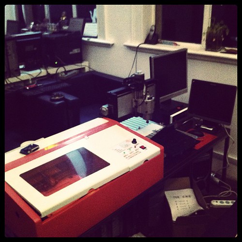
The engraver came with some exceedingly shite Chinese software (Moshi Engraver), but I did know that, and had ordered a cnc controller board with the idea of retrofitting that in. (its actually in the photo above funnily enough)
It has sat in the office mildly unused, but still in my thoughts.
One of my clients finally asked what was that large orange thing upstairs, and I dragged it out and setup for them to show off some test paper cuts.
Tomorrow will take a closer look at working out the pinouts as I didn’t get very far today in getting EMC2 talking nicely to to the Y axis (which was the goal for tonight).
Long term will be interested in making it work as a printer driven hardware device, but for now EMC2 is good enough.
http://www.laoslaser.org/ is making interesting progress in that regard, and I might look at talking directly to the Engraver factory about integrating and making a few with a few to selling a *decent* version.
As this will be a work in progress, here are the links that will be useful.
Some need a vee pee en to view in China sadly.
http://www.cnczone.com/forums/laser_engraving_cutting_machines/138554-cheap_laser_cutter_modifications.html
http://www.thinkhaus.org/2010/06/19/howto-turn-a-cheap-chinese-laser-engraver-into-a-pretty-good-laser-cutter/
http://www.stephenhobley.com/blog/2011/04/15/upgrading-a-laser-cutter-from-china/
http://www.andyslater.com/laser-cutting/cnc-conversion.html
http://dank.bengler.no/-/page/show/5473_connectinggrbl
http://www.synthfool.com/laser/
http://www.laoslaser.org/
This was posted by myself over at BimmerForum’s, but as China’s Firewall is being particularly unpleasant these days about what sites I can and cannot visit, I thought I’d repost it here, so its more accessible for me.
Note – I no longer own a 7 series, so any requests for modded rom’s should probably be accompanied with nice gifts to persuade me to do the work involved 🙂
As I saw people asking about Tuned ROM’s in another post I thought I’d do some research.
Its quite niche – hence the ridiculous pricing people charge for roms – time is money though!
Here’s my research so far. I’m basing it on the E32 735iL 1989/1990, as thats what I own (and can test for).
Googling for E32 735iL gives:
ELECTRONIC CONTROL UNIT, DME MOTRONIC
BOSCH 0261200179
BMW 1730697
*26SA0840*
Vehicle Applicability:
1986-1993
BMW 3′ E30 320i Touring 2.0 95kW/129PS (M20/ 206EE/KA)
BMW 5′ E34 535i 3.4 155kW/211PS (M30/346KB)
BMW 6′ E24 635CSi 3.4 155kW/211PS (M30 B35)
BMW 7′ E32 735i 3.4 155kW/211PS (M30/ 346KB/EC)
BMW 7′ E32 735iL 3.4 155kW/211PS (M30/ 346KB/EC)
ELECTRONIC CONTROL UNIT, DME MOTRONIC
BOSCH 0261200179
BMW 1722611
*26RT2794*
Vehicle Applicability:
1986-1993
BMW 3′ E30 320i Touring 2.0 95kW/129PS (M20/ 206EE/KA)
BMW 5′ E34 535i 3.4 155kW/211PS (M30/346KB)
BMW 6′ E24 635CSi 3.4 155kW/211PS (M30 B35)
BMW 7′ E32 735i 3.4 155kW/211PS (M30/ 346KB/EC)
BMW 7′ E32 735iL 3.4 155kW/211PS (M30/ 346KB/EC)
ETK however says
No.Description Supplement Qty Part Number Price
01AT-Control unit Motronic HARDWARE 1.3 1 12141738168 ENDED
01AT-Control unit Motronic HARDWARE 1.3 1 12141748258 $813.86
Whatever the actual revision used, its pretty clear we have a v1.3 Motronic.
Wiki (
) says:
|
The Motronic 1.1 System was used by BMW from 1987. This was then superseded in 1988 by the Motronic 1.3 system[6] that was also used by PSA on some XU9J-series engines (which previously used Motronic 4.1).[5]
The Motronic 1.1 and 1.3 systems are largely similar, the main improvement being the increased diagnostic capabilities of Motronic 1.3. The 1.3 ECU can store many more detailed fault codes than 1.1, and has a permanent 12-volt feed from the vehicle’s battery which allows it to log intermittent faults in memory across several trips. Motronic 1.1 can only advise of a few currently-occurring faults.[6] The systems include a knock sensor for ignition timing adjustment and the option for a lambda sensor, enabling their use with catalytic converter-equipped vehicles.[5] The ECUs have 2 injection outputs, and the injectors are arranged in 2 "banks" which fire once every two engine revolutions. In an example 4-cylinder engine, one output controls the injectors for cylinders 1 and 3, and the other controls 2 and 4. The system uses a "cylinder ID" sensor mounted to the cam-shaft to detect which cylinders are approaching the top of their stroke, therefore which injector bank should be fired. During start-up (below 600 RPM), or if there is no signal from the cylinder ID sensor, all injectors are fired simultaneously once per engine revolution.[6] |
DME / ECU 1.3 Info.
Tuning is set in 2D map.
Motronic 1.3 from 1989: The fault code memory is extended to contain all fault codes that are detected by the EMS.
In vehicles sold in the USA, when the ECU detects that a some faults are present it earths pin 15 and the Check Engine warning lamp on the dash will light. The lamp will stay lit until the fault is no longer present. A warning lamp is not fitted to vehicles sold in other markets. The faults that will turn on the lamp are mainly those concerned with emissions. Other faults are logged by the ECU but the lamp will remain out.
ECU (DME) sensors run off 5v
Download extended info here – http://www.opel-scanner.com/files/DME_1.1_1.3.pdf
DME bootup: (roughly paraphrased)
Interestingly enough I got to learn this properly via the tips and tricks for checking why the car doesn’t start..
Ignition switched on:
ECU earths 85 , 36 which causes relay to close and 30 is connected to 87 starting the fuel pump. (30+87 can be bridged manually under the green relay to test pump). Its opened for +- 1 second.
Next up it reads values from the CAS (Pulse Sensor). If it reads a speed signal (aka is it turning), so fuel pump stays on.
CAS is used to time the pulses (read from each turn of the flywheel), this is checked against the map file for correct speeds (need to use a multiplier for the map values vs the flywheel pins).
The Motronic ECU contains a fuel map with an injector opening time for basic conditions of speed and load. Information is then gathered from engine sensors such as the AFS, CAS, CTS, and TS. As a result of this information, the ECU will look-up the correct injector pulse duration right across the engine rpm, load and temperature range.
The injectors are arranged in two banks with injectors 1 and 3 (4 cylinder) or 1, 3 and 5 (6 cylinder comprising one bank, and injectors 2 and 4 (4 cylinder) or 2, 4 and 6 (6 cylinder) making up the other bank. Each bank is connected to the ECU via an independent ECU pin.
The Motronic 1.1 & 1.3 multi-point injection system pulses the injectors semi-sequentially and once every two engine revolutions. During engine start-up below 600 rpm the ECU pulses all injectors simultaneously. Once 600 rpm has been attained and if the ECU has received a signal from the CID sensor, each injector bank will be pulsed alternatively according to which pair of cylinders are approaching TDC. If a signal is not received from the CID sensor the injectors will remain on simultaneous operation. However, if the CID sensor subsequently sends a signal to the ECU after the engine has commenced running, the ECU will pulse the injectors semi-sequentially after the next deceleration phase – even if the CID sensor then ceases to send a signal.
—
Motronic troubleshooting (aka code readout)
The fault codes for these systems will appear on the check engine light when you turn the ignition key to the On position (but dont start it), then: fully depress the accelerator pedal, then fully release it. Repeat the depress,release cycle 5 times fairly quickly, but not too fast. It should be completed in a few seconds. What you are doing here is clicking the wide open throttle switch then the idle switch each 5 times. This signals the Motronic unit to send the fault codes by flashing the Check Engine light. You should see the light flash once then it will start flashing the 4 digit codes. If there are no faults, you should see the 1444 code (and 2444 if you have a 12 cylinder). The codes appear as a series of flashes for each digit. The flashes indicating one digit are about 1 second apart, the next digit appears after a couple second interval.
Get the codes from: http://www.unofficialbmw.com/repair_faqs/motronic.html
Other notes:
CPU most likely 8051
EEPROM 26C256, so 32KB / (32768 byte) chip. 28 pin.
Can also use a 64KB chip, just ground the relevant pins for which 32kb to use or burn one rom at appropriate location. Useful for running 2 tunes – eg original and second.
Tools available for this eg http://www.moates.net/font-size-12ti….html?cPath=31
Should run from a AT29C256 or similar.
ECU interesting pinouts:
Pin 55 TX
Pin 13 RX
Pin 2/19/24/26/14 GND
File layout (unchecked)
AFR idle: 0x662E (pos 26158)
AFR partial: 0x6662
AFR full: 0x6640
ign idle: 679A
ign partial: 0x67FE
ign full: 0x67CC
Sample bin file here: ftp://anonymous@bmw-wiki.org/ROMs/Mo…y-Motronic.bin
(I’m having issues downloading that from China, so haven’t checked it yet against the alleged layout).
Table calculations:
fuel maps correspond to (value/128 +1)*lambda_1
Bosch-Motronic f(n) = (n-30) x 0.75
some Bosch f(n) = (n-509) x 0.75
Bosch KE-Motronic und Mono-Motronic
f(n) = [(255-n)/6] +1
Motronic info
Very useful info for looking this up from http://motronic.ws/map201.htm
Maps 20 bytes each
Other thoughts – now we know what pinouts / values are expected in the system, guess just need to see what equipment provides appropriate inputs. eg, replace expensive spares with cheaper/better modern versions.
Most of the differences are usually in the mounting afaik, not the tech.
Motronic pinouts and board details here – http://www.e34.de/tips_tricks/motronic/m1_3.pdf
Lots of people working on this kind of thing with software like tunerpro / xdf (map) files.
*Good* forum for info (although not relevant to the Bosch ECU’s, but concepts / strategies same)
http://www.thirdgen.org/techboard/di…uide-book.html
The motronic 1.3 software in most of the E32’s should be fairly easy to modify – its all been documented well online before, so just a matter of getting a few rom files for specific models, and comparing tables.
Shogun has at least one rom (as he’s burning and selling them according to another post).
I can extract the current one from my DME and make a bin file for comparison.
We also have the rom from ftp://anonymous@bmw-wiki.org/ROMs/Mo…y-Motronic.bin
Should be enough to see where the changes are for the E32 / 8051CPU Motronic 1.3 anyway, so that I can tweak.
Another lucky thing is that I also used to write embedded software on 8051 cpu years ago (although I’ve forgotten it all by now)
Any interest in this from others (I’ll need more rom’s though)?
27
IP Cam Hacking – pt#3
I’ve finally received my 2nd camera, so I can now start working properly on it (assuming I get some free time too!)
High resolution photos of the board are below:
Main parts used are:
RAM – Winbond W9812G61H-6 (2M)
According to the data sheet, that 2M X 4 BANKS X 16 BITS SDRAM @ 3.3V / 166MHz/CL3
Data sheet is here – http://jp.ic-on-line.cn/IOL/datasheet/w9812g6ih_4223255.pdf
Flash – Spansion S29AL016D (2M)
Other boards are populated with different providers – some people have Samsung flash…
Mine has the Spansion onboard both units. Its programmable onboard (via the uBoot)
Data sheet here – http://www.datasheetpro.com/259722_view_S29AL016D_datasheet.html
Sound Card – ALC203
This is obviously used as the BSP for the Novotel provides sample code for that card, making their life easier…
Data sheet here – http://realtek.info/pdf/alc203.pdf
Wired Ethernet – Davicom DM9161AEP (10/100 Ethernet)
Data sheet here –
http://www.davicom.com.tw/userfile/24247/DM9161AEPProductBrief_v1.0.pdf
8 Port Relay Driver (for the motors etc) – ULN2803
Data sheet here – http://www.rentron.com/Files/uln2803.pdf
More info / explanation here – http://wiki.answers.com/Q/What_is_Relay_driver_ULN2803
Wifi – RALINK 2571 (on daughterboard). Wireless G
This is a USB based chipset, so we’re using 4 usb connector pins for this one.
No datasheet, as Ralink are dicks.
CPU – ARM7 N745CDG (Arm 7 by Nuvoton)
Lot of info for chip available at Nuvoton.
W90N745 makes use of the ARM7TDMI microprocessor core of ARMR and 0.18um production to achieve standard operation at 80MHz. 128-Pin LQPF packing is also used to save electricity and lower costs. The built-in 4KBytes I-Cache and 4KBytes D-Cache of W90N745 can also be set as On-Chip RAM according to the needs of product developers. With regards to system integration, W90N745 is suitable for network-related applications such as management switch, IP cameras, VoIP and printer servers.
Features
* One Ethernet MAC
* One USB 2.0 full speed Host controller
* One USB 2.0 full speed Host/Device controller
* AC97/I2S
* 4 UARTs
* I²C Master
* 31 GPIOs
* Power Management
Data sheets – http://www.nuvoton.com/hq/enu/ProductAndSales/ProductLines/ConsumerElectronicsIC/ARMMicrocontroller/ARMMicrocontroller/NUC745A.htm
The uclinux sample distribution and files can be downloaded here – http://www.metavert.com/public/NO-SUPPORT/NUC700%20Series%20MCU%20uCLinux%20BSP.zip
I’m just waiting on a JLINK USB adaptor, then I’m ready to roll.
[Updates]
David M from comments at http://irishjesus.wordpress.com/2010/03/30/hacking-the-foscam-fi8908w/#comments provided his rom sizing from his device, I’ve got some notes on that here.
MAC Address : 00:30:10:C1:D0:39
IP Address : 0.0.0.0
DHCP Client : Enabled
CACHE : Enabled
BL buffer base : 0×00300000
BL buffer size : 0×00100000
Baud Rate : -1
USB Interface : Disabled
Serial Number : 0xFFFFFFFF
For help on the available commands type ‘h’
Press ESC to enter debug mode …
bootloader > ls
Image: 0 name:BOOT INFO base:0x7F010000 size:0×00000038 exec:0x7F010000 -af
Image: 7 name:linux.bin base:0x7F020000 size:0x000BB334 exec:0×00008000 -acxz
Image: 6 name:romfs.img base:0x7F0E0000 size:0x0008D000 exec:0x7F0E0000 -a
My notes:
Image: 0 name:BOOT INFO base:0x7F010000 size:0×00000038 exec:0x7F010000 -af
[Image 0 is 38 bytes (small!).
Boot info is not the bootloader – 38bytes is way too small for that.
It actually stores our bootloader config settings.
eg ip address, cache setting, boot loader buffer address etc.
Our initial settings are below:
MAC Address : 00:30:10:C1:D0:39 (should be changed, this Mac range belongs to Cisco!)
IP Address : 0.0.0.0 (unset)
DHCP Client : Enabled (pulls ip from dhcp..)
CACHE : Enabled (onboard chip cache)
BL buffer base : 0×00300000
BL buffer size : 0×00100000
Baud Rate : -1 (unset / so defaults to 115,200,8,n,1)
USB Interface : Disabled (NC745 has no USB for bootloader)
Serial Number : 0xFFFFFFFF (unset)
-af indicates Active (a) , and is a Filesystem image (f)]
Image: 7 name:linux.bin base:0x7F020000 size:0x000BB334 exec:0×00008000 -acxz
[Image 7 is our OS – Linux 2.4.20 ucLinux Not sure why Maverick didn’t build on 2.6, there is more hardware support. Probably time dependant – 2.6 may not have been available, plus the Nuvoton sample code is also 2.4 based…
-axcz says active (a) executable (x) copied to ram (c) compressed (z) ]
Image: 6 name:romfs.img base:0x7F0E0000 size:0x0008D000 exec:0x7F0E0000 -a
[Our rom image – aka userland stuff. This is where we’ll be putting our own code. Looks like its stuck quite high up in the flash, although doesn’t need to be given size of the Linux rom. We have plenty of room available.
We’ll need to make appropriate changes to Image 6 size on flashing
-a says active partition.]
21
IPCam Hacking – pt#2
Finally got a chance to play around with the second ipcam I bought.
This one is a little bit smarter than the previous one – its running off an ARM5ARM7 CPU (Nuvoton NUC745ADN), so has a bit more oomph. 16M ram is a whole lot more to play with for a start! The last device only had 16KB, so this puppy can be taught to do some tricks!
Serial was a little bit trickier to solder on this time – my initial connectors were too small, so had to resolder with larger ones, and I managed to mess up a tad. Never said my soldering was any good 😉
Getting it to talk to the computer was a bit painful too – eventually I settled on 115,200 8,n,1, xon/xoff which should have worked the first time around, but I was getting garbage.
Probably flow control (xon/xoff), as fiddling with the connections got it going eventually.
First output from the board is below – this is from a clean boot (with no ethernet or wifi).
W90P745 Boot Loader [ Version 1.1 $Revision: 1 $ ] Rebuilt on Dec 10 2009

Memory Size is 0x1000000 Bytes, Flash Size is 0x200000 Bytes

Board designed by Winbond

Hardware support provided at Winbond

Copyright (c) Winbond Limited 2001 - 2006. All rights reserved.

Boot Loader Configuration:
MAC Address : 0E:F2:B3:DC:08:05
IP Address : 0.0.0.0
DHCP Client : Enabled
CACHE : Enabled
BL buffer base : 0x00300000
BL buffer size : 0x00100000
Baud Rate : -1
USB Interface : Disabled
Serial Number : 0xFFFFFFFF
For help on the available commands type 'h'
Press ESC to enter debug mode ......
Cache enabled!
Processing image 1 ...
Processing image 2 ...
Processing image 3 ...
Processing image 4 ...
Processing image 5 ...
Processing image 6 ...
Processing image 7 ...
Unzip image 7 ...
Executing image 7 ...
Linux version 2.4.20-uc0 (root@maverick-linux) (gcc version 3.0) #1013 Èý 12ÔÂ 2 13:17:32 CST 2009
Processor: Winbond W90N745 revision 1
Architecture: W90N745
On node 0 totalpages: 4096
zone(0): 0 pages.
zone(1): 4096 pages.
zone(2): 0 pages.
Kernel command line: root=/dev/rom0 rw
Calibrating delay loop... 39.83 BogoMIPS
Memory: 16MB = 16MB total
Memory: 14376KB available (1435K code, 288K data, 40K init)
Dentry cache hash table entries: 2048 (order: 2, 16384 bytes)
Inode cache hash table entries: 1024 (order: 1, 8192 bytes)
Mount-cache hash table entries: 512 (order: 0, 4096 bytes)
Buffer-cache hash table entries: 1024 (order: 0, 4096 bytes)
Page-cache hash table entries: 4096 (order: 2, 16384 bytes)
POSIX conformance testing by UNIFIX
Linux NET4.0 for Linux 2.4
Based upon Swansea University Computer Society NET3.039
Initializing RT netlink socket
Starting kswapd
Winbond W90N745 Serial driver version 1.0 (2005-08-15) with no serial options enabled
ttyS00 at 0xfff80000 (irq = 9) is a W90N745
Winbond W90N7451 Serial driver version 1.0 (2005-08-15) with no serial options enabled
ttyS00 at 0xfff80100 (irq = 10) is a W90N7451
I2C Bus Driver has been installed successfully.
Blkmem copyright 1998,1999 D. Jeff Dionne
Blkmem copyright 1998 Kenneth Albanowski
Blkmem 1 disk images:
0: 7F0E0000-7F16D3FF [VIRTUAL 7F0E0000-7F16D3FF] (RO)
AM29LV160DB Flash Detected
01 eth0 initial ok!
which:0
PPP generic driver version 2.4.2
Linux video capture interface: v1.00
Winbond Audio Driver v1.0 Initialization successfully.
usb.c: registered new driver hub
add a static ohci host controller device
: USB OHCI at membase 0xfff05000, IRQ 15
hc_alloc_ohci
usb-ohci.c: AMD756 erratum 4 workaround
hc_reset
usb.c: new USB bus registered, assigned bus number 1
hub.c: USB hub found
hub.c: 2 ports detected
usb.c: registered new driver audio
audio.c: v1.0.0:USB Audio Class driver
usb.c: registered new driver serial
usbserial.c: USB Serial Driver core v1.4
_____ ____ _ ____
|__ / _| _ \ / \ / ___|
/ / | | | | | |/ _ \ \___ \
/ /| |_| | |_| / ___ \ ___) |
/____\__, |____/_/ \_\____/
|___/
ZD1211B - version 2.24.0.0
usb.c: registered new driver zd1211b
main_usb.c: VIA Networking Wireless LAN USB Driver 1.13
usb.c: registered new driver vntwusb
usb.c: registered new driver rt73
dvm usb cam driver 0.0.0.0 by Maverick Gao in 2006-8-12
usb.c: registered new driver dvm
dvm usb cam driver 0.1 for sonix288 by Maverick Gao in 2009-4-20
usb.c: registered new driver dvm usb cam driver for sonix288
NET4: Linux TCP/IP 1.0 for NET4.0
IP Protocols: ICMP, UDP, TCP
IP: routing cache hash table of 512 buckets, 4Kbytes
TCP: Hash tables configured (established 1024 bind 2048)
VFS: Mounted root (romfs filesystem) readonly.
Freeing init memory: 40K
BINFMT_FLAT: bad magic/rev (0x74202d74, need 0x4)
BINFMT_FLAT: bad magic/rev (0x74202d74, need 0x4)
Shell invoked to run file: /bin/init
Command: mount -t proc none /proc
Command: mount -t ramfs none /usr
Command: mount -t ramfs none /swap
Command: mount -t ramfs none /var/run
Command: mount -t ramfs none /etc
Command: mount -t ramfs none /flash
Command: mount -t ramfs none /home
Command: camera&
[8]
Command: sh
no support
Sash command shell (version 1.1.1)
/> hub.c: connect-debounce failed, port 1 disabled
new USB device :80fd7e04-fed640
hub.c: new USB device 1, assigned address 2
dvm cmos successfully initialized
dvm camera registered as video0
new USB device :80fb0204-fed640
hub.c: new USB device 2, assigned address 3
idVendor = 0x148f, idProduct = 0x2573
Wait for auto-negotiation complete...ResetPhyChip Failed
video0 opened
1
1
1
1
1
1
set resolution 5
set brightness 144
set contrast 3
set sharpness 3
set mode 2
__pthread_initial_thread_bos:34c000
manage pid:16
audio_dev.state not AU_STATE_RECORDING
wb_audio_start_record
=> usb_rtusb_open
retide_ddns.c: can not get server dns.camcctv.com ip
ntpc.c: can not resolve ntpserver(time.nist.gov)'s ip
get oray info
upnp get ip error
inet_sr.c INET_rinput 321
action===1
options==33
inet_sr.c INET_setroute 75
*args===255.255.255.255
*args===netmask
*args===eth1
inet_sr.c INET_rinput 321
action===1
options==33
inet_sr.c INET_setroute 75
*args===default
*args===gw
*args===eth1
MlmeAssocReqAction(): WPA2/WPA2PSK fill the ReqVarIEs with CipherTmp!
3
3
3
3
3
3
Initially I had the board setup on its own without the camera attached, but the boot scripts require it connected, otherwise they reboot..
Ostensibly, this is the same hardware as the fi8908w (who are just reselling the OEM version with marginally different firmware as far as I can tell).
Next step is to setup a cross compiler for uclinux so I can make some binaries, and test.
Luckily all the available tools are open source / free. Yay!
I’m in contact with the factory, and they’ll be sending an SDK over at some point soonish, although its only in Chinese.
Luckily for me, that shouldn’t be a problem, as i’m reasonably capable at groking both code, and simplified chinese 🙂
ucLinux should be easy enough to build a rom image for though – tons of examples, and I already have a few firmware files to compare.
It shouldn’t be too hard for me to roll another firmware with ssh installed, so that we can get in without serial, that would be more useful for others too.
I’ve had a quick look inside the folders in the device from the device itself – fairly minimal, pretty much the only binaries are the necessary ones.
My initial aim is to redo the UI to a nicer one, and fix some of the more glaring bugs. The factory people are at a trade show in Taiwan this week, so hopefully next week I’ll get some dev tools (otherwise its reverse engineering, bleh…).
Some more people are playing with these as well (links below):
http://irishjesus.wordpress.com/2010/03/30/hacking-the-foscam-fi8908w/
http://www.gadgetvictims.com/2009/12/bring-your-fi8908w-paperweight-back-to.html
Unfortuanately for me, both are variably accessible. WordPress is available this week woohoo, but its an on / off dealio with the GFW…, so I might have to stop commenting there once the government decides if WordPress is “teh evil” again.
The irishjesus blog guy has done some of the harder bits like file extraction already (although not strictly necessary, as there are existing tools for that kind of thing).
—
Updates
Have some docs from the factory now, see attached file for the CGI spec.
I have others, but not so relevant especially for those than don’t read Chinese!
Data sheet for the Chip and build instructions here –
When I was younger, I used to like taking things apart. I still do that, but they tend to work better these days, hehe
This last few weeks I’ve been playing with IP Camera’s for a pet project that started off as a request over Skype for info about surveillance.
As the ever useful Taobao is full of vendors selling the same 4 or 5 camera’s for reasonable prices I ordered a couple to take a peek at.
I’ve only taken one apart so far – the really really cheap one that I installed in the office so I can get a look at who comes up the stairs without having to move my fat ass out of the chair. A quick shortcut in FF, and it works quite nicely as a separate browser window in the corner of the desktop.
Onto the discovery phase 🙂
I had a quick spin with NMAP, but other than discovering that they rather naughtily misuse a Mac Address assigned to the evil Cisco, not much help.
Also nothing appeared to be running on any other ports than the web port 🙁
nmap -A 192.168.0.88
Starting Nmap 5.00 ( http://nmap.org ) at 2010-04-13 19:27 CST
Interesting ports on 192.168.0.88:
Not shown: 999 filtered ports
PORT STATE SERVICE VERSION
80/tcp open http?
|_ html-title: IPCamera
1 service unrecognized despite returning data. If you know the service/version, please submit the following fingerprint at http://www.insecure.org/cgi-bin/servicefp-submit.cgi :
SF-Port80-TCP:V=5.00%I=7%D=4/13%Time=4BC45529%P=i686-pc-linux-gnu%r(GetReq
SF:uest,2E1,"HTTP/1\.1\x20200\x20OK\r\nExpires:\x200\r\nConnection:\x20clo
SF:se\r\ncache-control:\x20no-cache\r\n\r\n\r\n
SF:IPCamera\r\n\r
SF:\n\r\n\r\n\r\n\r\n
SF:\r\n\r\n\r\n\r\n\r\n\r\n\r\n<BODY\x20onLoad=\" SF:doPop\(\);\">\xb6\xd4\xb2\xbb\xc6\xf0\xa3\xac\xc4\xfa\xb5\xc4\xe4\xaf\x
SF:c0\xc0\xc6\xf7\xb2\xbb\xd6\xa7\xb3\xd6\xbf\xf2\xbc\xdc\xa3\xa1</BODY></ SF:NOFRAMES>\r\n</FRAMESET>\r\n\r\n</HTML>\r\n")%r(FourOhFourRequest,1DF,"
SF:HTTP/1\.1\x20200\x20OK\r\nConnection:\x20close\r\ncache-control:\x20no-
SF:cache\r\n\r\n<HTML>\r\n<HEAD>\r\n<TITLE></TITLE>\r\n<meta\x20http-equiv SF:=\"Content-Type\"\x20content=\"text/html;\x20charset=gb2312\"></HEAD>\r
SF:\n<BODY\x20BGCOLOR=\"#C4CEEF\"\x20onLoad=\"window\.status='\xbb\xb6\xd3 SF:\xad\xca\xb9\xd3\xc3\xcd\xf8\xc2\xe7\xc9\xe3\xcf\xf1\xbb\xfa!';return\x SF:20true;\">\r\n\r\n
<TABLE\x20WIDTH=140\x20BORDER=0\x20CELLSPACING=0\x20C SF:ELLPADDING=0>\r\n
<TR>\r\n\t
<TD\x20HEIGHT=80\x20ALIGN=center\x20BGCOLOR= SF:\"#C4CEEF\"><FONT\x20color=\"#FF6633\"\x20size=\"\+2\"\x20FACE=\"Arial\ SF:"><B>IP\x20Camera</B></FONT></TD>
\r\n</TR>
\r\n</TABLE>
\r\n\r\n</BODY>\r
SF:\n</HTML>\r\n");
MAC Address: 00:0A:42:33:66:54 (Cisco Systems)
Warning: OSScan results may be unreliable because we could not find at least 1 open and 1 closed port
OS fingerprint not ideal because: Missing a closed TCP port so results incomplete
No OS matches for host
Network Distance: 1 hop
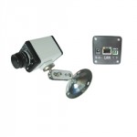
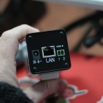
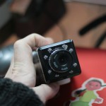
Next up is the usual dissection. I had done some minor googling on the device I bought, which is basically this below:
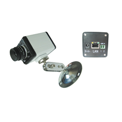
As its an OEM product, this is available under a whole bunch of different names – mostly with IP-510 or similar in the title, eg LTI-510 etc.
For a cheap OEM product, it actually seems to be reasonably well made though – the Case is an nice and solid aluminium sheath that looks like its been repurposed from something else, and the board itself is suprisingly well diagrammed. Its almost made for hacking!
Chips onboard are as follows:
25.0618mhz crystal from TXC – bonus points for why its 25mhz. Reply in the comments 🙂
Davicom DM9008AEP, TRC9016NLE (both for Ethernet. imho Davicom is a second-rate Realtek)
ViMicro VC0528BRVC (Camera processor / CCD Controller)
And last, but not least, our CPU, which is an 8051, although not from ATMEL.
Part number on that is C8051F340. My first guess is that it incorporates some integrated flash on there for firmware. Unfortunately its likely to be all C and Assembler, and the last time I did embedded 8051 stuff was in the early 90’s.
Google confirms it – basically its an all in one controller with 32 or 64KB onboard, and roughly 4k ram. Woohoo!
Datasheet here – http://www.alldatasheet.com/datasheet-pdf/pdf/182721/SILABS/C8051F340.html
Good news is that the board has serial out clearly labeled on the top left side. Better news is that the chip has an onboard debug mode, so I don’t even need any ICE (In Circuit Emulation) tools should I want to take a look. Bad news is that I’m probably going to be too lazy to do it, as its more work and less fun than the second one I bought, which has Linux running on it.
That said, this one is cheap. Real cheap. Cheap enough that its probably worth knocking out a decent firmware, and reselling it with a better UI, and more features.
Might be possible, although anything more than whats there is probably stretching it given the ram / storage constraints. Looks like its all offboard processing/streaming for this model!
There are also some unpopulated spots on the board, which I strongly suspect would be for audio, given the board has a MIC input and no Mic, and the main controller is a ViMicro, which supports MP3 output also…
I’ll see if I can find a firmware file, and do a disassembly, or more probably see what I get out of the serial port connection in the near future.
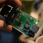
Photos below. [Excuse the pasty white hands, its still winter for some reason in Shanghai, despite being April… Oh global warming. Where art thou, when I needest thee!]:
Some further files for the curious here –
Archives
- November 2024
- November 2019
- October 2019
- August 2019
- April 2019
- February 2017
- September 2016
- June 2016
- May 2016
- September 2015
- August 2015
- June 2015
- April 2015
- December 2014
- October 2014
- September 2014
- July 2014
- June 2014
- April 2014
- October 2013
- July 2013
- May 2013
- April 2013
- March 2013
- January 2013
- December 2012
- October 2012
- August 2012
- July 2012
- June 2012
- May 2012
- April 2012
- March 2012
- December 2011
- November 2011
- October 2011
- September 2011
- July 2011
- May 2011
- April 2011
- March 2011
- February 2011
- January 2011
- December 2010
- November 2010
- October 2010
- September 2010
- August 2010
- July 2010
- June 2010
- May 2010
- April 2010
- March 2010
- February 2010
- January 2010
- December 2009
- November 2009
- October 2009
- May 2009
- April 2009
- March 2009
- February 2009
- January 2009
- December 2008
- November 2008
- October 2008
- September 2008
Categories
- Apple
- Arcade Machines
- Badges
- BMW
- China Related
- Cool Hunting
- Exploits
- Firmware
- Food
- General Talk
- government
- IP Cam
- iPhone
- Lasers
- legislation
- MODx
- MySQL
- notice
- qmail
- requirements
- Reviews
- Service Issues
- Tao Bao
- Technical Mumbo Jumbo
- Things that will get me censored
- Travel
- Uncategorized
- Useful Info
